Aluminum Extrusion Dies: This is What Designers Should Know
The aluminum extrusion process can be used to produce a wide range of shapes. You may be most familiar with standard shapes such as angles, channels, and tubes — all of which are commonly available from extruders and distributors.
However, the flexibility of the extrusion process gives product designers the opportunity to create a wide range of custom profiles for applications in the architectural, automotive, electronics, and other industries.
Every unique extrusion shape requires its own die and the appropriate tooling to go with it. Let’s talk about what an extrusion die is, the three different types of dies, and the support tooling required.
Table of Contents
What is an Aluminum Extrusion Die?
An extrusion die is a thick steel disk with an opening — and malleable aluminum alloy passes through it during the extrusion process.
The opening in the die matches the cross-sectional profile that’s specified by the extrusion designer.
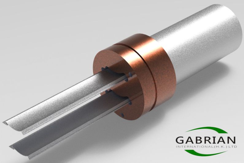
Aluminum billet material (top right) passing through an extrusion die (middle) and coming out as extruded profiles (bottom left)
Typically, dies are produced from H13 steel and heat-treated, making them strong enough to withstand the intense pressure — up to 15,000 tons of it — that can be involved in the extrusion process.
They come with support tools — also usually made from H13 steel — to help withstand this pressure and lengthen die life.
With that in mind, let’s discuss the different types of dies that are used for extrusion.
The 3 Types of Extrusion Dies
There are three types of extruded shapes — solid, hollow, and semi-hollow — each of which has specific characteristics and has different die and tooling requirements. Let’s take a look at what they are.
#1 – Solid Dies
Solid dies produce shapes that do not have any enclosed voids or openings — for example, solid bars, angles, and channels.
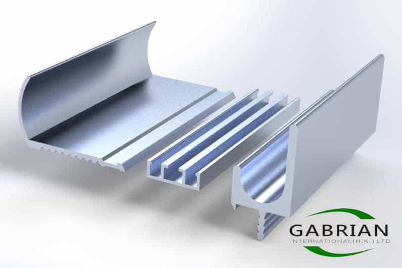
Three examples of solid extrusion shapes
The dies used to extrude solid shapes generally fall into three categories:
- Flat-face dies
- Pocket dies, and
- Feeder dies.
A flat-face die — as the name implies — has a totally flat face with openings that match the shape of the extrusion exactly. The material from the aluminum billet goes directly through these openings.
A pocket die has a cavity built into the front of it that is slightly larger than the width of the profile. This enables the aluminum billets to weld together and allows for continuous extrusion.
A feeder die has a separate feeder plate that gets pinned or bolted onto the front of it. Like the pocket die, it allows for continuous extrusion. Also called a weld plate, the feeder can help control contour or spread the aluminum to different areas of the die. Another advantage of a feeder die is that it prevents direct contact between the billet and the face of the die during billet deformation.
Flat-face die (left), pocket die (center), and feeder plate (right)
The next type of die we will cover is the hollow die.
#2 – Hollow Dies
A hollow die produces a shape that has one or more voids— for example, a simple rectangular tube or a complex, multi-void t-slot.
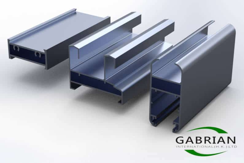
Three examples of hollow extrusion shapes. Note the void in the middle of each one.
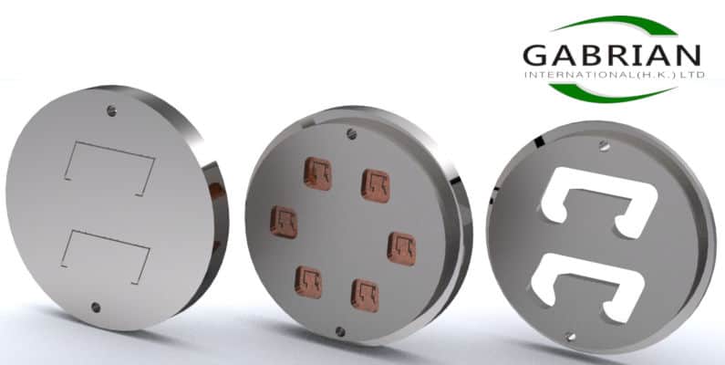
To extrude hollow shapes, a porthole die is generally used. It is made up of two interlocking pieces — the mandrel and the cap.
The mandrel forms the internal features of the profile and has multiple portholes separated by webs or legs for support.
The cap forms the external features of the profile and is assembled with the mandrel.
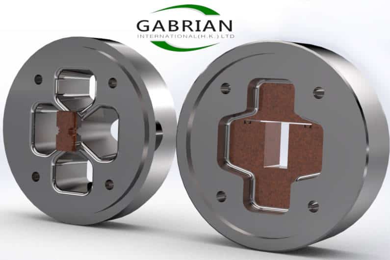
A mandrel (left) and die cap (right)
During the extrusion process, hot aluminum billet material will enter through the mandrel and exit from the cap.
With that in mind, what is a semi-hollow die?
#3 – Semi-hollow Dies
Similar to a hollow shape, a semi-hollow shape has a void or voids. The difference, though, is that the voids are not fully enclosed — they have a gap or opening.
This is somewhat of a hybrid between the previous two types. As it turns out, there is often a very fine line between solid shapes and semi-hollow ones.
For example, a wide aluminum channel has a partially enclosed void and is considered solid. A very narrow channel, on the other hand, might be considered semi-hollow.
So how can we distinguish between solid and semi-hollow profiles?
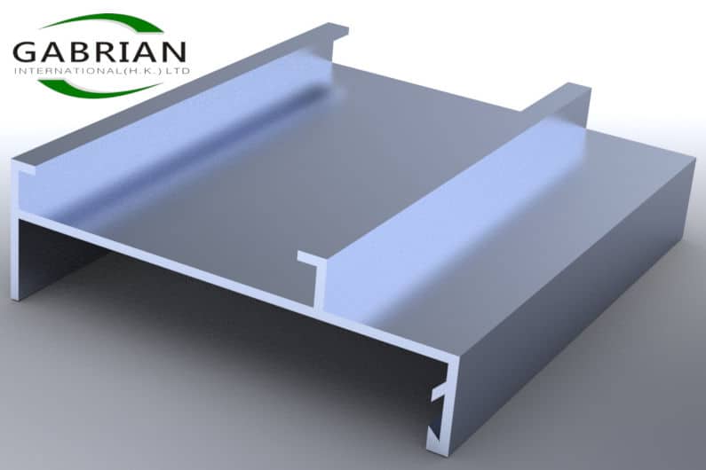
A solid profile with wide channels designed into it
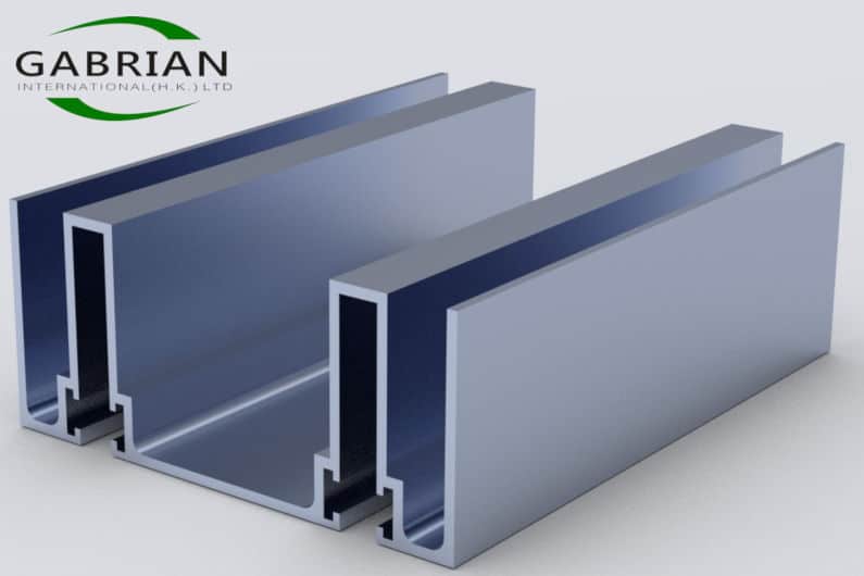
A semi-hollow profile with narrow channels designed into it
To make this distinction, a formula called the “tongue ratio” is used. The tongue ratio is defined as (Area/Gap²).
In essence, the larger the void area and the narrower the gap, the more likely it is for a shape to be defined as semi-hollow.
The tongue ratio is important because the higher the tongue ratio, the more difficult a shape becomes to extrude.
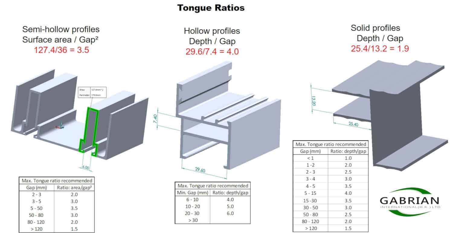
See the above image with maximum tongue ratios recommended for the three types of dies. (Click to enlarge)
Remember that high levels of force are being applied to the die. Because of this, the void/tongue area becomes prone to breakage as the tongue ratio goes higher.
Generally, a porthole die with a mandrel and a cap is used, as is the case with hollow dies. But a semi-hollow die may require more complexity in design to help strengthen the tongue area and lengthen the die’s life.
Another key to lengthening the life of a die is its tooling.
How Does Aluminum Extrusion Tooling Work?
Every die needs the appropriate tooling to help support it. With so much pressure coming from the extrusion press, strong tooling is needed.
A die’s “tool stack” also helps to control the speed of extrusion and allows for improved tolerances.
The most commonly used tools are backers and bolsters.
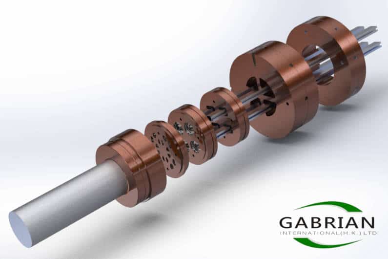
Extrusion die (bottom left), backer (middle), and bolster (top right) with an extrusion passing through them
A backer sits directly behind the extrusion die and has the same diameter. But the opening in the backer is somewhat wider than that of the die. It is pinned or bolted to it.
Its main function is to reduce die deformation and prevent fracturing, with so much pressure being applied to the die. The backer geometry will closely match the contour of the die to provide maximal support.
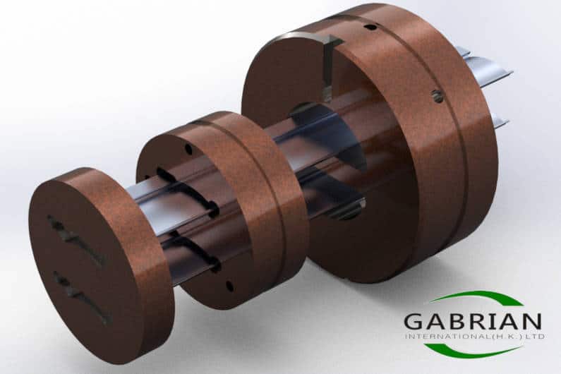
A bolster sits behind the backer and is generally the same width as the die ring (which is used to hold the whole tool stack in place). It has a wider opening than the backer and is pinned or bolted to it.
In some cases, a sub-bolster is used, which sits behind the bolster and provides additional support.
A bolster and sub-bolster can sometimes be shared between several dies that have the same geometry layout.
Example of a complete tooling assembly. From bottom left to top right – Die ring, mandrel, cap, backer, bolster, sub-bolster
As we’ve said, support tooling is required to withstand the pressure of the extrusion process.
This leads us to another important point — that the life of your die will partly be determined by how well you have designed your extrusion shape for manufacturability.
To improve manufacturability, collaboration between the designer, tool shop, and extruder is key.
The Success of Your Project Depends on Collaboration
An extrusion die receives thousands of tons of pressure from the extrusion ram. Over time this takes a toll on the die and it will eventually fail.
Design for manufacturability will influence:
- The life of your die and tooling
- The cost of your die and tooling
That’s why it makes sense to engage in discussions with the die shop and manufacturing engineers as early as possible to ensure that you are making good design choices.
In some cases, the die shop and the extruder might be two separate companies. But at Gabrian, our extrusion partners in India have their tool & die shops in-house.
We recommend making your design process a collaborative one to help ensure the success of your project and to avoid wasting valuable time.
If you’d like to learn more about how to optimize your part design for the extrusion process, download our Aluminum Extrusion Design Guide.
Aluminum Extrusion Design Guide
Aluminum extrusions can be designed to fit a wide range of products used in various industries. But product designers often have difficulty achieving optimal extrusion profile design and reducing manufacturing costs.
In this guide, we provide 11 tips to help you optimize your designs for the extrusion process.
Download Aluminum Extrusion Design Guide

Reduce manufacturing costs, maximize quality, and improve production speeds.