If you’re in the process of designing an aluminum part or product by die casting, you may feel overwhelmed by the number of factors to take into account at this stage. After all, perfecting the design phase is one of the most crucial steps in successfully and efficiently manufacturing die-cast products.
Luckily, our experts have extensive knowledge of how to design for optimum aluminum die casting production, and this article will give you some insight into what they know. We will cover how to design a product for efficient and effective manufacturing, as well as some of the most common considerations you need to take into account when designing a product to be made through die casting.
Table of Contents
Aluminum Casting Design Best Practices: Design for Manufacturing
Design for Manufacturing (DFM) is a term often used in engineering. It refers to the process of optimizing production to make it as simple and cost-effective as possible. DFM focuses heavily on the manufacturing methods and processes used.
One of the main advantages of DFM is that it allows problems with the production method to be detected and solved early on in the design phase. At this stage, issues are much less expensive to resolve than when they are discovered during or after the production run. Applying DFM techniques allows for a reduction in the costs of manufacturing while maintaining a good or better standard of quality.
In order to optimize the production process of aluminum die casts, the following objectives should be targeted:
- Use the least amount of casting material possible,
- Ensure that the part or product will easily come out of the die,
- Minimize the solidification time for a casting,
- Reduce as much as possible the number of secondary operations, and
- Ensure that the final product will perform as required.
The best way to meet these optimization objectives is to take into account the design considerations discussed in the following sections during the design phase.
9 Aluminum Die Casting Design Considerations to Keep in Mind
This section gives you an introduction to some of the most common considerations when designing a product to be made using die casting. These tips align with DFM best practices and are recommended by the North American Die Casting Association.
1. Parting line
As you already know from our previous article, the die casting process involves a die that is usually divided into two halves (although it can be divided into more), one of them mobile and the other static, that come together to form the mold where the molten metal will be injected. The parting line of a die-cast component is the interface where the two halves of the die come together.
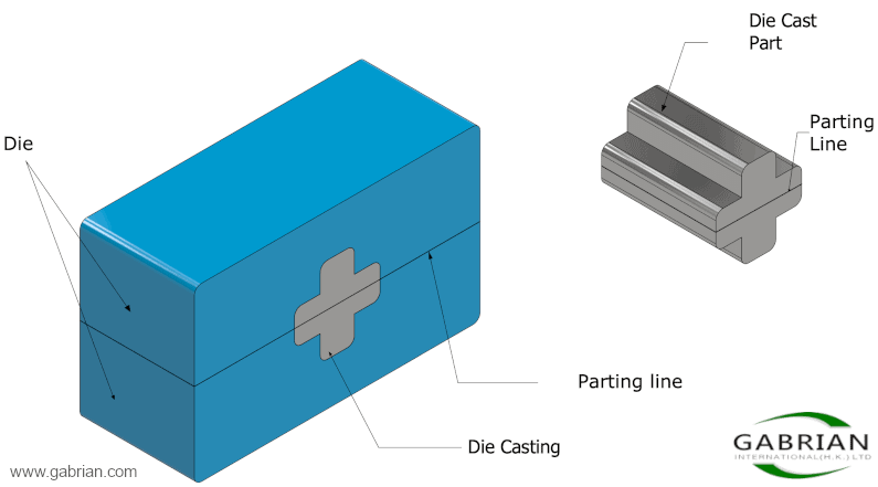
During the design process, choosing where the parting line will be positioned is one of the first things you have to decide, as it has an effect on other design specifications.
An important aspect of the location of the parting line is that it will also be the place where a common die-casting defect, known as flash, will be located. The flash has to be removed by a secondary process after the cast has solidified, which is why it should be designed to be easily accessible by the trimming machinery.
2. Shrinkage
Shrinkage is a very common and unavoidable phenomenon that happens in most castings, and aluminum is no exception. As the molten metal starts to cool down from melting temperature to room temperature, the cast will shrink towards its center.
Castings commonly shrink between 0.4-0.6% of their volume, which can help the product to be ejected from the external walls of the die. Unfortunately, it can also constrict around any internal protrusions on the mold, making ejection difficult under those circumstances. In these situations, you can make use of a draft to reduce shrinkage and facilitate easier removal of the cast.
3. Draft
In the context of die casting, a draft is a small taper or inclination that can be seen on the sides of the mold that allow for easy ejection. You might have seen this taper in other kinds of molds, such as baking pans for muffins and bread, where the sides have a slight angle instead of being completely vertical.
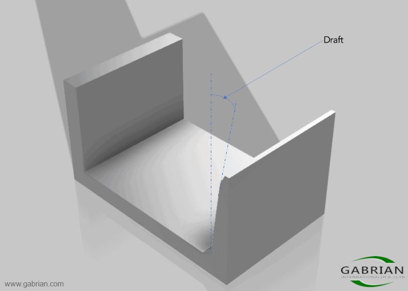
This draft has to be included in all cast surfaces that are parallel to the movement of the die, as this will facilitate easier ejection. Failure to include it can cause the cast to be very difficult, if not impossible, to remove without damaging it.
Keep in mind that the amount of draft, expressed in either millimeters or degrees, will vary considerably throughout most designs. For example, outside walls require only a relatively small draft as the cast shrinks away from them, but inside walls and holes require a larger draft as the metal shrinks and grips around them.
4. Wall Thickness
In order to ensure rapid production, reduce material waste, and create a successful product, wall thickness has to be carefully considered.
A wall design that is too thin could prevent an adequate flow of the molten metal, making the metal solidify before the mold is completely filled. Thin walls can also be susceptible to warping when post-mold machining forces are applied. Excessively thick walls, on the other hand, not only waste casting material, but they increase solidification times, potentially eliminating the fast production cycle advantage of high-pressure die casting.
Wall thickness should also be as uniform as possible. This allows the molten metal to flow easily, which is essential for having an effective solidification process that ensures optimal cast strength and reduces the possibility of cast defects. If variations in thickness are necessary, gradual transitions should be used instead of sudden changes.
5. Fillets and Radii
Fillets and radii are curved junctures between two surfaces that would otherwise create a sharp edge. The following image shows an example of a part that incorporates each of these features. The key difference is that fillets exist on the internal edges of the part while Radii are found on the external edges.
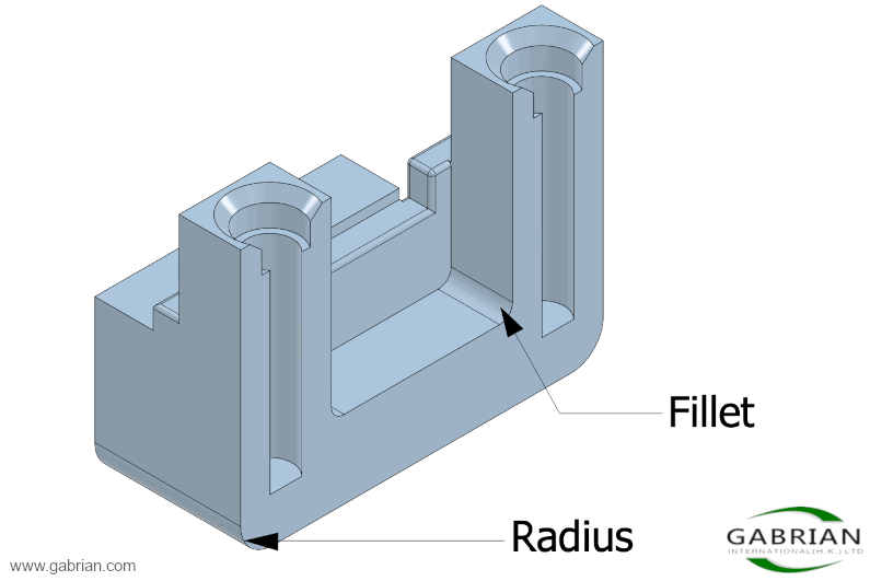
These rounded edges are extremely important in die casting design, as having them allows the metal to flow easily when injected. Sharp corners in the die create turbulence in the metal flow, which can reduce the strength of the cast component. Radii can also eliminate the need for trimming sharp corners and edges through a secondary operation.
6. Bosses
Bosses are protruding features of cast products that are normally used as standoffs or mounting points. This video displays a good visual for what a boss is by showing a boss being added to a doorknob. Including bosses in your design can prevent the need for time-consuming boring operations as a secondary process.
Since major changes in wall thickness can cause uneven shrinkage and sinking that negatively impact a part’s appearance and even its integrity, bosses must be designed to maintain a uniform wall thickness relative to the surrounding part. A common method for maintaining a uniform wall thickness is to add a hole to the center of the boss.
You should also consider adding ample fillets at the location where the boss connects to the rest of the cast, to allow for proper metal flow. A proper draft angle must also be considered for bosses, as well as ribs to increase its strength.
7. Ribs
Ribs are small bridges of material that can be added between walls to increase their strength without adding too much metal. They also help molten metal to reach every part of the die by increasing the available flow pathways.
The image below shows a cast aluminum product that includes a boss which will be used for mounting, and three ribs connected to an outer wall, which increases the structural soundness of the boss.
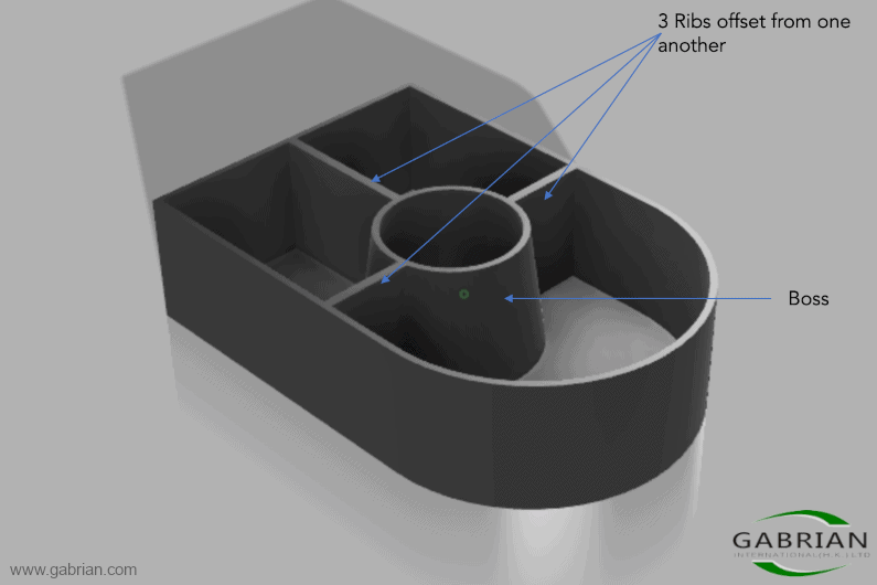
In accordance with best practices, ribs are usually added to a design in odd numbers or are otherwise offset from one another in order to prevent stresses impacting ribs that are adjacent to each other.
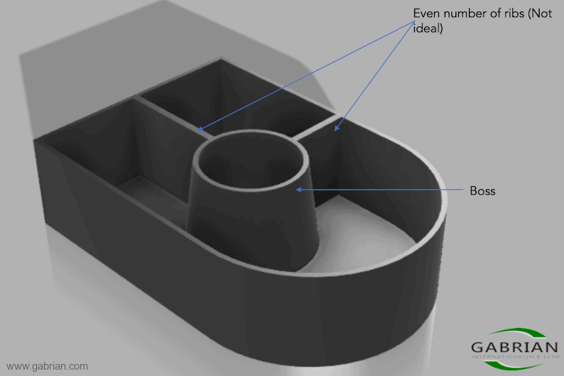
The image above shows an example of a design with an even number of ribs, going against best practices.
8. Undercuts
Undercuts are known in manufacturing as recessed surfaces that cannot be accessed with a straight tool. The nature of undercuts can prevent die separation and cast ejection after solidification as the die will be essentially “gripping” the cast product, which is why careful design is important.
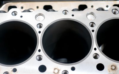
The following image shows a component with and without an undercut. You can see that the figure on the right has a depressed surface where the small and big cylinders connect which would make it impossible to eject from the die.
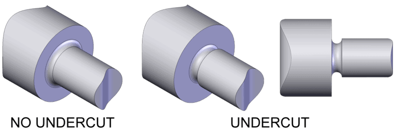
Source: Wizard191, CC BY-SA 3.0, via Wikimedia Commons.
If an undercut is essential to your design, you can design your parting line around the undercuts. Another method is to use dies that are made up of more parts than just the core and cavity, like in the following animation, or by using semi-permanent molds.
Source:LaurensvanLieshout, CC BY-SA 3.0, via Wikimedia Commons.
These methods, however, increase the cost and complexity of the die considerably. Additionally, semi-permanent milds, which include the use of sand cores, cannot be used in high-pressure die casting processes.
9. Holes and Windows
Accounting for the holes and windows needed in a final die cast part during the design phase can significantly reduce the amount of post-molding machining required. Eliminating or minimizing drilling, milling, and other machining activities wherever possible by thoughtful mold design can drastically improve manufacturing times.
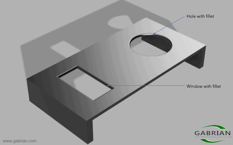
Holes and windows have the added benefit that they generally do not introduce too many new challenges when incorporated into a design. However, you should still take into account that they will make the molten metal flow more complex, which could lead to turbulence and potential casting flaws associated with turbulence. Adding fillets and radii to any edges on holes and windows can help mitigate this issue.
It is also important to remember that holes and windows in the cast can grip the die during ejection, meaning you have to incorporate drafts around them during the design phase.
Conclusion
As you have now seen, designing for aluminum die casting presents many challenges. This article gives you an idea of some of the most important aspects that have to be considered during the design stage, though it’s possible that you may encounter even more obstacles impacting your specific project.
In this article, we’ve briefly touched on secondary, or post-molding, operations as an aspect of die casting design, particularly since minimizing them is a good way to optimize the manufacturing process. To get a better understanding of what they entail, what applications they are relevant for, and more view our article on secondary operations for die cast parts.
If you have any doubts or need assistance in setting up your aluminum die casting project, please contact us for more guidance. You can also learn more about Gabrian’s aluminum high-pressure die casting services.